Lithium Battery Nominal Voltage: Cells, Modules and Packs
Lithium Battery Nominal Voltage: Cells, Modules and Packs
Nominal voltage is the number printed on every lithium cell, yet it is the most misunderstood spec in procurement. “3.7 V” is not the voltage you design to, and “48 V” pack is not a single cell multiplied. Getting the levels wrong means BMS trips, chargers that never finish, and packs that sag under load. This guide walks the voltage chain from cell to module to pack, and tells you what a real lithium battery manufacturer actually specifies at each stage.

What “nominal” really means
Nominal voltage is a labeled average, not a real operating point. An LFP cell is called 3.2 V nominal but sits at 3.65 V fully charged and about 2.5 V empty; an NMC cell is called 3.7 V but ranges from 4.2 V down to 2.8–3.0 V. The number exists so buyers can compare families, not so engineers can size chargers. Design to the actual charged and cut-off voltages, and treat nominal as a label, because every downstream calculation depends on the real range, not the rounded name.
Cell-level voltage by chemistry
LFP’s flat curve keeps voltage near 3.2 V for most of the discharge, which simplifies BMS thresholds but makes voltage-based SoC poor. NMC and NCA rise to 4.2 V and fall steeply, giving more energy per cell but tighter protection windows. A sodium-ion battery runs a lower window, roughly 1.5–2.0 V per cell, which changes the series count needed for a given pack voltage. These per-cell ranges are the seed of every module and pack voltage, so they belong in the requirement document before any series math.
Building modules from series and parallel
Cells combine in series (S) to raise voltage and in parallel (P) to raise capacity. A 4S LFP module is four cells in series: roughly 12.8 V nominal, 14.6 V charged. A 4S2P is that stack duplicated in parallel for double capacity at the same voltage. The art is balancing series count against the BMS’s manageable window and parallel count against current handling. Over-series a string and the BMS balancer struggles; under-parallel and one cell’s weakness caps the whole pack. The module is where voltage and capacity are actually set.
Pack voltage: the series math
| Pack label | Chemistry | Series count | Charged voltage |
|---|---|---|---|
| 12 V | LFP | 4S | ~14.6 V |
| 24 V | LFP | 8S | ~29.2 V |
| 48 V | LFP | 16S | ~58.4 V |
| 48 V | NMC | 13S | ~54.6 V |
The table shows why “48 V” is ambiguous: an LFP 48 V pack is 16 cells, an NMC 48 V pack is 13 cells, and their charged voltages differ by nearly 4 V. A charger or BMS sized for one will mistreat the other. Always state chemistry and series count, not just the marketing voltage, or you will buy a pack your existing charger cannot finish.
BMS voltage windows and cutoffs
The BMS enforces the real limits: over-voltage cutoff at full charge, under-voltage cutoff at empty, and balancing across the series string. For an LFP 16S pack the over-voltage trip is near 58.4 V and the under-voltage near 40 V, while an NMC 13S pack trips around 54.6 V and 39 V. A battery application solutions program that mixes chemistries must keep separate BMS profiles, because porting an LFP window onto NMC leaves cells over-charged or under-utilized. The cutoff values are the pack’s actual safety envelope, so they are a first-class spec, not a default.
Charger matching
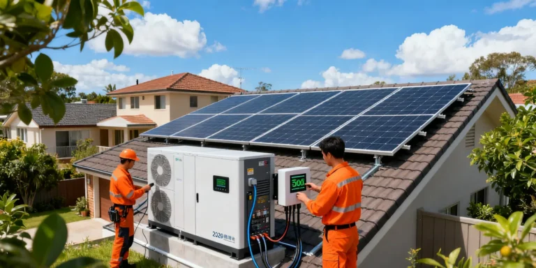
A charger must match the pack’s chemistry, series count and charge profile (CC-CV with the right termination current). A 54.6 V NMC charger on an LFP 16S pack (needs ~58.4 V) will never fully charge it; an LFP charger on NMC will over-voltage. For a home energy storage system, the inverter’s charge stage must be configured to the exact cell count and chemistry, and the setting must survive a firmware update. Mismatched charging is the quietest way to strand capacity and the most common field complaint we investigate.
Voltage sag under load
Nominal voltage says nothing about sag. Under high current the pack voltage dips by I×R, and a weak series group sags hardest, tripping the under-voltage cutoff prematurely. This is why two packs with identical nominal voltage behave differently under load: internal resistance and balancing decide the usable floor. A semi-solid-state battery tends to hold voltage better per kilogram because the same current is a lower C-rate, but the sag physics are unchanged. Spec the pack’s voltage at your operating C-rate, not at rest, because rest voltage is a lie you only discover under load.
Series imbalance and balancing
In a series string, one weak group limits the whole pack, and without balancing the strong groups get cut off early while the weak one is still full. Passive balancing bleeds the high groups; active balancing moves charge and is better for large banks. The balancer’s current must suit the pack: a 50 mA passive balancer on a 200 Ah bank is cosmetic. Confirm the balancing current and the BMS’s ability to report per-group voltage, because that report is how you catch an imbalanced string before it caps capacity or trips a cutoff during a critical load.
Module-to-pack wiring and busbars
Voltage is only as good as the connections carrying it. Busbars and connectors must carry the continuous and peak current with margin, sized by I²R heating at the peak C-rate, not the average. A loosely torqued lug at high current is a heater, not a conductor, and the failure is silent until it is a fire. Specify the connector part number, the torque and the peak amp rating in the build document, and verify a sample at incoming inspection. The cells may be perfect while the interfaces quietly become the weakest link, and the BMS cannot protect a connection it does not measure.
Procurement voltage checklist
- State chemistry and exact series count, not just the marketing voltage label.
- Confirm charger and BMS profiles match the real charged and cut-off voltages.
- Request pack voltage at your operating C-rate, accounting for sag.
- Verify balancing current suits the pack capacity.
- Specify busbar and connector ratings for the peak current with margin.
- Require per-group voltage telemetry to catch series imbalance early.
Naming standards buyers should enforce
Insist that every voltage figure in the spec carries its chemistry, series count and level, cell, module or pack. A bid that says only “48 V” is not a specification, it is an ambiguity that will surface as a mismatched charger or a BMS that trips early. Write the required nominal, charged and cut-off voltages explicitly, and reject any quote that cannot state them. This single discipline prevents more field failures than any amount of post-sale troubleshooting, because it forces the supplier to commit to the actual electrical envelope up front rather than hiding behind a marketing label that fits three different packs. The cost of writing the numbers is ten minutes; the cost of discovering the mismatch in the field is a returned shipment and a lost customer.
Voltage and the protection chain
Voltage limits cascade through the protection chain: the cell’s own window sets the module window, which sets the pack window, which the BMS enforces and the charger must respect. A break anywhere, wrong series count, mis-set cutoff, charger that overshoots, stresses the cells or leaves capacity unused. The BMS is the last line, but it should not be the only line; the charger, the connector rating and the enclosure thermal path all assume the voltage envelope is correct. Review them as one chain in the design review, not as separate components owned by different engineers, because a voltage error propagates across all of them and the failure looks like a cell problem when it is a system one that no single subsystem owner caught.
Field verification of voltage
Once installed, verify the voltage chain with a loaded measurement, not a resting one. Put the pack under your real operating current and confirm the bus voltage, the per-group voltages and the charger termination all match the spec. Resting checks hide sag and imbalance that only appear under load. Log the numbers at commissioning so you have a baseline to judge aging against. A five-minute loaded voltage check at install catches most of the errors that would otherwise return as mysterious capacity complaints months later, and it costs nothing but the discipline to do it. Make the loaded check a line item in the acceptance test so it is never skipped under schedule pressure, and the field failure rate drops noticeably.
Frequently asked questions
Is nominal voltage the operating voltage? No—it is a labeled average; design to the real charged and cut-off range.
Why are two “48 V” packs different? LFP 48 V is 16S (~58.4 V charged), NMC 48 V is 13S (~54.6 V); chargers are not interchangeable.
What causes premature cutoffs? Series imbalance and voltage sag under load; fix with balancing and C-rate-aware sizing.
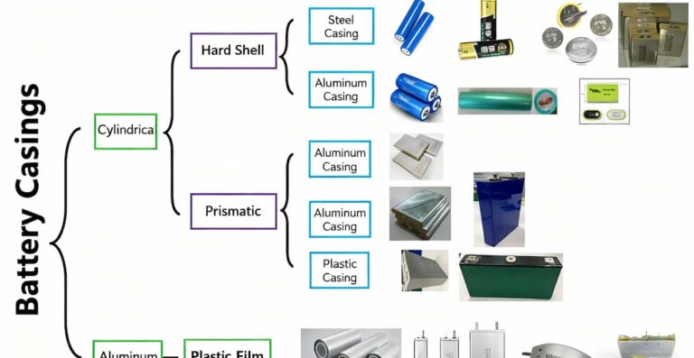
Does form factor change voltage? No—voltage is set by chemistry and series count, not by prismatic, cylindrical or pouch.
Written by Karl at China Battery Technology. Give us your chemistry and target voltage and we will set the series count—request a quote for a matched pack and charger.
Related Reading
- battery application solutions hub
- Lithium Battery Energy Density: Why It Drives Design
- NMC vs LFP Cost and Safety Trade-offs in 2026