How Lithium Batteries Work: A Practical Primer for Engineers
How Lithium Batteries Work: A Practical Primer for Engineers
If you spec, integrate or buy lithium packs but came from another discipline, this primer closes the gap between the catalog and the cell. It explains the components, the ion movement, and the electrical quantities you actually use—voltage, capacity, energy, C-rate—in plain engineering terms. The goal is that after reading, you can read a datasheet critically and talk to a lithium battery manufacturer without the sales deck doing the thinking for you, and you will know which numbers on the page are real constraints and which are marketing best-cases dressed up as specifications.

The basic cell: three components
A lithium cell has three active parts plus a separator. The cathode (positive electrode) is a lithium metal oxide; the anode (negative electrode) is typically graphite; the electrolyte carries lithium ions between them; and the separator keeps the electrodes apart while letting ions pass. The “lithium” in lithium-ion refers to the ion that shuttles back and forth—not a metallic lithium electrode in the commercial cell. That distinction matters: the commercial cell is safe enough to ship, while a pure lithium-metal electrode is the harder, still-emerging solid-state target. Everything else in the pack exists to manage these three components, and a failure in any surrounding system is what turns a safe cell into a hazard.
Cathode and anode: where energy lives
Energy is stored in the chemical difference between the two electrodes. The cathode chemistry decides the voltage and the energy density: LFP (iron phosphate) is stable and long-lived but lower voltage; NMC (nickel-manganese-cobalt) is higher energy but needs more care; LCO (cobalt oxide) is dense and common in phones. The anode is usually graphite, which stores lithium by sliding ions into its layered structure. The choice of cathode is the single biggest design decision a cell maker makes, and it is why two “lithium” cells can behave nothing alike. A semi-solid-state battery changes the electrolyte and often the anode to push density, but the cathode logic still applies, and the voltage class you design around is still set by the cathode material chosen.
Electrolyte and separator: the ion highway
The electrolyte is a lithium salt dissolved in an organic solvent—a liquid that conducts ions but not electrons. The separator is a microporous polymer film that blocks electronic contact (preventing a short) while allowing ion flow. If the separator is punctured or the electrolyte dries, the cell can internally short and heat. This is why physical abuse, overcharge and manufacturing defects are dangerous: they breach the very thing keeping the electrodes apart. The electrolyte’s flammability is also why enclosure and BMS design are safety-critical, and why non-flammable solid electrolytes are the solid-state promise, because removing the liquid removes the easiest thing in the cell to set on fire under abuse or fault conditions.
Intercalation: how ions move
During discharge, lithium ions leave the anode, cross the electrolyte and separator, and insert (“intercalate”) into the cathode lattice, while electrons travel the external circuit doing work. During charge, an external source pushes the ions back to the anode. Crucially, the ions insert into host structures rather than plating as metal in normal operation—which is what keeps the process reversible for thousands of cycles. When charging is too cold or too fast, that orderly insertion fails and metallic lithium plates instead, permanently losing capacity and risking dendrites. Intercalation is the reversible heart of the cell; plating is its failure mode, and recognizing the boundary between them is the single most useful concept an integrator can carry from this primer into a real design review.
Voltage, capacity and energy
| Quantity | What it is | Units |
|---|---|---|
| Cell voltage | Potential difference, ~3.0–4.2 V per cell | Volts (V) |
| Capacity | Stored charge available | Amp-hours (Ah) |
| Energy | Voltage × capacity | Watt-hours (Wh) |
| Power | Energy delivered per time | Watts (W) |
The table is the vocabulary you need. A 3.7 V, 100 Ah cell holds about 370 Wh; string cells in series to raise voltage, in parallel to raise capacity. Energy (Wh) is what runs your load; power (W) is how fast you draw it, expressed as C-rate. Confusing Ah with Wh is the most common spec error—a 12 V 100 Ah pack (1,200 Wh) is not interchangeable with a 48 V 100 Ah pack (4,800 Wh) even though both are “100 Ah.” Always convert to watt-hours when comparing packs, because that is the only unit that lets you honestly compare a 12 V pack against a 48 V pack against a 52 V pack across different voltage classes and chemistries.
The charge and discharge cycle
Discharge lowers the state-of-charge and the terminal voltage roughly together; charge raises both. A constant-current/constant-voltage (CC-CV) charger pushes a fixed current until the cell reaches its top voltage (say 4.2 V for NMC, 3.65 V for LFP), then holds voltage while current tapers—that CV tail is where the last percent of charge trickles in and where plating risk is highest if rushed. A good BMS enforces these limits per cell; a missing or mis-set limit is how packs swell and fail. Understanding CC-CV explains why a “full” charge takes longer than the bulk and why fast-charging skips part of the tail at the cost of some life, and it lets you read a charger spec and know whether it will treat your cells kindly or abuse them for the sake of a few saved minutes.
State of charge vs voltage
State-of-charge is not a direct measurement—it is inferred from voltage, current integration (coulomb counting) and temperature. Voltage alone is a poor SoC indicator because it sags under load and recovers at rest, so a BMS blends methods. This is why a cheap pack shows a jumpy “fuel gauge” while a good one is steady: the estimation algorithm and current sensor quality differ, not the cells. For a home energy storage system, accurate SoC drives everything from dispatch to warranty, so the BMS estimation quality is a first-class spec, not a detail, and the difference between a trustworthy gauge and a guessing one is the difference between a system you can automate and one you must babysit.
C-rate and internal resistance
C-rate is current divided by capacity: 1C draws the full capacity in an hour. A 100 Ah pack at 1C delivers 100 A. Internal resistance converts current to heat and voltage sag; a high-resistance (aged) cell sags under load and heats, accelerating fade. That resistance is why a pack’s delivered capacity drops as you pull harder—the headline Ah is only valid at the test rate. Match the pack’s C-rate to your load, and confirm the BMS and connector are rated for the peak, not just the average. A sodium-ion battery currently targets lower C-rate stationary uses, so its rate limits differ from NMC and must be checked against your duty, because assuming one chemistry’s rate envelope applies to another is a classic and expensive integration error.
Chemistry families compared
| Chemistry | Voltage (nom.) | Energy density | Cycle life | Best for |
|---|---|---|---|---|
| LFP | 3.2 V | Low–moderate | 3,000–6,000+ | Stationary, motive |
| NMC | 3.6–3.7 V | High | 1,000–2,000 | Weight-sensitive |
| LCO | 3.6–3.7 V | Very high | Moderate | Consumer electronics |
| Sodium-ion | ~3.0 V | Moderate | Emerging | Stationary, low-cost |
The table is the cheat-sheet you will return to. Pick chemistry by the duty: LFP for life and safety, NMC for energy per kilogram, sodium for abundant low-cost stationary. A battery application solutions program should let the application choose the chemistry, not the other way around, because the wrong chemistry is expensive in either dollars or kilograms, and the cost of forcing an NMC pack into a stationary bank or an LFP pack into a drone is paid in money or in failed field performance respectively.
The BMS layer
The cell is dumb; the BMS is the brain. It measures per-cell voltage and temperature, cuts off over- and under-voltage, limits current and short-circuits, balances cells, and reports state-of-charge and state-of-health over a bus (CAN, RS485, SMBus). Without it, a lithium pack is a controlled hazard. The BMS thresholds are chemistry-specific—an LFP cutoff near 3.65 V would deep-discharge an NMC pack meant for 2.5 V—so the firmware must match the cells. When a pack fails, it is usually the BMS or its integration, not the cells, which is why BMS ownership and tuning matter as much as cell grade, and why a buyer who cannot see or adjust the BMS firmware is buying a black box they may not be able to fix when something goes wrong in the field.
Thermal behavior
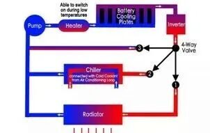
Lithium cells like 15–35 °C and resent heat and cold charging. Heat accelerates the SEI growth that permanently consumes lithium; cold charging causes plating. The enclosure must shed heat at the operating C-rate and include a low-temperature charge lockout. Thermal runaway is a chain reaction where one failing cell heats neighbors; good pack design spaces cells, adds thermal barriers and lets the BMS disconnect before propagation. None of this is optional for a safe pack, and it is why a bare cell plus a cheap protector is not a product—the thermal and electrical system around the cell is the product, and the cell is only the energy source the system is built to manage safely and predictably over years of service.
Why cells are built in series and parallel
A single cell is only ~3.2–3.7 V, so packs string many in series (S) to reach the system voltage (e.g., 13S for ~48 V) and in parallel (P) to multiply capacity (e.g., 4P for more Ah). A “13S4P” pack is 13 series groups of 4 parallel cells. Series raises voltage; parallel raises capacity and spreads current so each cell sees a gentler C-rate. Mismatched cells in parallel cause imbalance and local heating, so cell matching at build and active balancing in service matter. The pack notation tells you the topology at a glance, and reading it tells you where the weak points and the BMS sensing points are, which is the first thing an experienced engineer checks before trusting a pack’s claimed performance in their application.
Safety fundamentals
Safety is layered: the cell chemistry sets the baseline, the separator and electrolyte contain the risk, the BMS enforces electrical limits, and the enclosure manages thermal and physical abuse. No single layer is sufficient. The practical buyer verifies the UN38.3 transport test, asks for the relevant IEC/UL-style safety reports, and confirms the BMS actually enforces limits rather than just reporting them. A pack that meets the cell-level standard but ships with a passive protector and no thermal path is not safe by association—the system must be designed as a system. Treat safety documentation as a selection criterion, not paperwork, because the paper is what lets the product ship across borders and what proves, later, that the design was sound when questioned after an incident.
Frequently asked questions
Is lithium-ion the same as metallic lithium? No—commercial cells use a graphite anode and shuttle ions; only emerging solid-state uses lithium metal.
Why convert to watt-hours? Because Ah alone ignores voltage; Wh is the true energy you can use to run a load.
What is intercalation? Ions insert into electrode host structures reversibly; plating instead is the failure mode.
Does the BMS really matter? Yes—most pack failures are BMS or integration faults, not cell faults.
Written by Karl at China Battery Technology. Describe your load and we will translate it into a pack—request a quote for an engineering review.
Related Reading
- battery application solutions hub
- IEC 62619 Explained: Stationary Battery Safety for Buyers
- IEC 62133: Portable Battery Safety for Medical and Consumer