Battery Application Solutions for Metal Foundry: Heat, Dust and Duty Cycles
Battery Application Solutions for Metal Foundry: Heat, Dust and Duty Cycles
A foundry floor is an electromagnetic and thermal filter for any battery system. Ambient temperatures near molten metal reach 60–80 °C at working height, an induction furnace throws electromagnetic interference across the whole floor, silica dust coats every connector, and molten metal fragments fly. Under those conditions a generic industrial battery fails fast and fails expensively. What works is a purpose-built battery application solutions package: sealed high-temperature cells, a cabinet that sits outside the radiant heat path, shielding on the BMS bus, and a charging schedule that exploits the foundry’s natural off-peak windows. This article covers the four duties where batteries genuinely belong in a foundry, the thermal engineering, the standards, and the commissioning checklist.
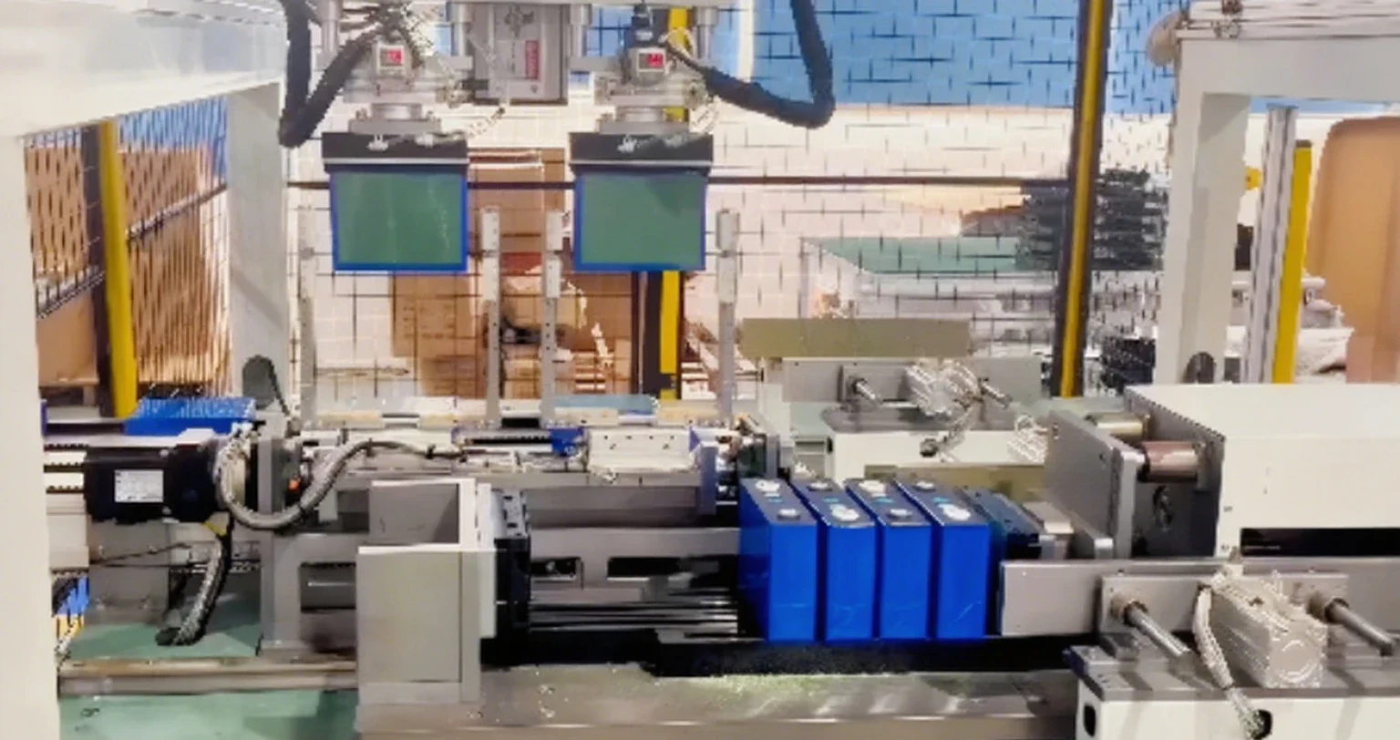
The Four Duties that Suit Battery Power
Not everything in a foundry should be electrified. Four duties benefit clearly. First, charging and nuisance buggies — the small vehicles that move sand, molds and scrap between stations run at 1–3 kW for hours and are the classic electrification target, because their duty cycle is regular enough to charge overnight. Second, mobile tracing and sensor equipment: thermocouple logging carts, infrared scan vehicles, and alloy identification guns that need portable power but have no mains nearby. Third, emergency and escape lighting plus gate and crane-route safety systems that must hold certification during a power failure. Fourth, and increasingly important, the instrumentation bus itself — weighbridge indicators, melt-shop telemetry and gas monitoring need a clean, ripple-free supply that does not depend on the plant’s noisy mains. Everything else — the ladle crane, the underwater riser, anything holding direct molten metal handle — stays on mains or diesels for good reasons.
Thermal Engineering Is the Whole Problem
A LiFePO4 cell loses roughly half its cycle life for every 10 K of sustained operation above the design point, so a pack sited in a foundry bay at 55 °C ambient with no airflow will not reach a third of its catalogue life. The three workable answers are: keep the pack out of the radiant zone entirely, in an air-conditioned or louvered cabinet at the wall at temperatures below 35 °C, which is the standard approach and the cheapest; use a high-temperature cell variant with a rated operating range to 70 °C, accepting a 20–30% capacity derate; or liquid-couple the pack to the plant’s chilled-water loop, which is over-engineering for anything under 20 kWh. Whichever route you take, the pack’s cell temperature must be measured and logged, because the BMS derating curve should start pulling current at 45 °C and reach hard cutoff at 65 °C — a pack that permits 70 °C continuous operation in a foundry is selling you short life, not robustness.
Dust, Vibration and the BMS Bus
Foundry dust is a fine silica and alumina powder that is abrasive and conductive when it holds moisture. Anything with an air path into the pack gets clogged; anything with an exposed connector gets a resistive film that eventually heats. The practical design rules are: IP65 or IP66 enclosures with filtered forced ventilation, positive-pressure air purge in the cabinet so dust cannot enter, sealed aviation-style connectors rather than screw terminals wherever a cable flexes, and a conformal coating on the BMS PCB because the controller board is the first thing to fail. Electromagnetic compatibility deserves special attention — an induction furnace produces fields that couple into long cable runs, so the pack’s communication bus must be twisted-pair with shielding and earthed at one point only, and the BMS must use an isolated RS-485 transceiver. Installing the pack’s DC output through a metal conduit with a ferrite-choke feed helps more than most vendors tell you.
System Comparison for Foundry Duties
| Duty | Battery type | Usable capacity | Charging window | Expected life |
|---|---|---|---|---|
| Charging / nuisance buggy | LiFePO4 48 V cabinet | 15–40 kWh | Off-peak, 6–8 h | 4000–6000 cycles |
| Scan and trace vehicles | LiFePO4 24 V portable | 2–6 kWh | Toolbox charge, 2 h | 3000–5000 cycles |
| Escape lighting / gate safety | LiFePO4 + external charger | 1–3 kWh | Mains, trickle | 10 years float service |
| Instrumentation and telemetry | LiFePO4 12 V sealed | 0.5–2 kWh | Solar or mains | 8–12 years |
| Mobile molten-metal sensors | High-temp LiFePO4, insulated | 0.3–1 kWh | Bench charger | 2000–3000 cycles |
Charging Strategy Around the Furnace Cycle
A foundry has a naturally structured day: the melt cycle runs 8–12 hours, then there is a pour window, then an off period. Charging should be scheduled to the off-peak electrical window and to the melt cycle rather than to the vehicle’s convenience — fleets that charge a 30 kWh buggy at 40 A overnight take 12 hours, which is fine, while a fleet that fast-charges mid-pour at 200 A will shorten pack life and deepen the plant’s peak demand. Where the plant has a demand tariff, the dispatch logic should cap site demand: charge at whatever rate keeps the total site import under the agreed kilowatt limit, which for a typical small foundry means a 30–60 A charge current even for a 40 kWh pack. Regen is worth mentioning — a downhill buggy or a crane lowering a load can return 10–20% of the energy spent raising it, and a regenerative controller on the buggy fleet is one of the cheapest efficiency wins on the floor.
Safety, Standards and Insurance
Foundry work carries an insurance and statutory inspection layer that batteries have to fit into. The pack needs a documented thermal runaway analysis, a vent path to outside the cabinet, and a fire-suppression option in the charging room — most plants accept a fire-resistant cabinet with automatic sprinkler head above the charge bay. Electrical installation must follow the national wiring rules, and the battery room must be separated from the melting hall by a fire-rated wall with a rated door. Where packs travel inside foundry vehicles, the vehicle itself must carry the certification for the installation, and the pack’s mass distribution changes the vehicle’s roll stability — a 400 kg battery low in a buggy is fine, the same pack high on a handling trolley is not. Guidance on industrial storage safety and installation practice is published by the U.S. Department of Energy, and the international cell and pack standards are catalogued by the International Electrotechnical Commission, whose IEC 62619 standard is the one most foundry specifications cite for stationary industrial cells. Ask your supplier for the test report against both, plus a UN38.3 summary if the pack ships by road.
Commissioning and Maintenance
Commissioning should follow a fixed sequence: verify cell voltage spread within 30 mV, confirm the BMS sees every cell and every temperature sensor, run a controlled discharge at 0.5C into a resistive load bank and log the voltage curve against the datasheet, then run the worst-case duty — a full buggy charge plus a simultaneous melt cycle — for 24 hours with temperature logging. After commissioning, the maintenance regime is short: a monthly visual check of enclosure seals and connector torque, a quarterly review of the cell voltage spread and the BMS fault log, an annual thermal-imaging pass over the DC terminations (a hot joint shows up months before it fails), and a capacity test at 24 months to confirm the pack is tracking the warranty curve. Over a 10-year horizon the pack cost is the smaller number; the unplanned stop of a pour line costs orders of magnitude more, which is the argument to specify a pack with spare capacity and a module-level replacement plan rather than the cheapest cabinet on the quote.
People Also Ask
Can batteries be used safely near molten metal? Yes, if the pack cabinet sits outside the radiant heat envelope with its cell temperature logged and the BMS derating below 45 °C; packs placed within a few metres of a ladle are the ones that fail, not the chemistry.
Which chemistry lasts longest in a hot industrial hall? LiFePO4, provided it stays below 40 °C cell temperature; a high-temperature cell variant helps only if the surrounding cabinet is cooled, because the cell inside a sealed hot enclosure will still cook.
How do I justify the cost to the plant? By comparing against the demand-charge penalty and the avoided shovel-and-diesel hours — a 30 kWh buggy fleet replacing two diesel units typically pays back in three to four years on fuel and maintenance alone, before the demand-charge saving.
Written by Karl at China Battery Technology. Request a quote.