The 2025 lithium battery voltage code: the material gene war from 3.7V to 4.7V
“When the Tesla 4680 battery pushes the voltage platform to 3.8V with a silicon oxygen anode, while the blade battery holds fast to the 3.2V lithium iron phosphate defense – the essence of the voltage difference is the ‘electron pulling force war’ between electrode materials. As an engineer involved in the development of the IEC 62660 standard, I will use the atomic movement under the transmission electron microscope to dismantle the material the material genetic code behind the voltage.”
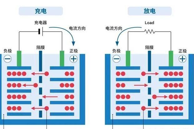
I. Birth of Voltage: The Electronic Playing Field of Positive and Negative Poles
1. Potential difference – the ‘genotype’ of voltage
Thermodynamic formula: U = E_cathode – E_anode
Lithium cobaltate positive electrode: 4.2V vs Li⁺/Li (cobalt 3⁺/4⁺ redox pair)
Graphite negative electrode: 0.1V vs Li⁺/Li (LiC ₆ embedded lithium reaction)
→ Theoretical voltage: 4.2V – 0.1V = 4.1V
Lithium iron phosphate dilemma:
Fe²⁺/Fe³⁺ redox potential is only 3.45V → voltage locked at 3.2-3.3V after matching graphite
2. Polarization effect – ‘attenuator’ of voltage
| Polarization type | generating mechanism | pressure drop | recovery speed |
|---|---|---|---|
| ohmic polarization | Ion migration is impeded | 0.05-0.15V | Disappears when current stops |
| electrochemical polarization | interfacial reaction delay | 0.10-0.30V | millisecond |
| concentration-difference polarization | Ion concentration gradient at the electrode surface | 0.20-0.50V | order of seconds |
Case: NCM811 battery 5C discharge, concentrated polarization led to a voltage plunge of 0.4V, the actual operating voltage fell from 3.7V to 3.3V
II.Material revolution: three battles of voltage leaping
1. Cathode materials: voltage ‘ceiling pusher’
High voltage triumvirate:
| makings | Voltage platform | energy density | Achilles’ heel |
|---|---|---|---|
| Lithium Cobaltate (LCO) | 3.9V | 180Wh/kg | Cobalt is expensive |
| Lithium Nickel Manganese Oxide (LNMO) | 4.7V | 220Wh/kg | Oxidative decomposition of electrolyte |
| Lithium-rich manganese-based (LRM) | 3.8V | 300Wh/kg | Voltage decay > 2mV/cycle |
Technical breakthroughs:
Fully fluorinated electrolyte: withstands high voltage of 4.7V (LNMO system), maintains 90.8% capacity for 1,000 cycles
Gradient coating: alumina coating inhibits Mn dissolution and reduces voltage decay rate by 40%.
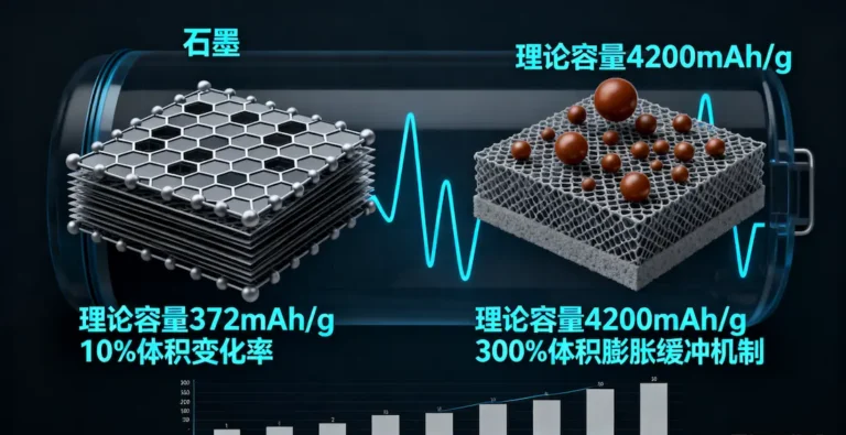
2. Negative electrode materials: the ‘invisible manipulator’ of voltage
Silicon-based anode trap:
Silicon embedded lithium level 0.4V → theoretical voltage of 3.8V with NCM anode
Actual polarization voltage increases by 0.25V due to volume expansion of 300% → working voltage is only 3.55V
Lithium titanate (LTO) subversion:
embedded lithium level 1.55V → low-temperature discharging at -30℃, although voltage is sacrificed (LNMO/LTO is only 3.2V)
3. Electrolyte: the ‘life and death defense’ of high voltage
4.5V curse: traditional LiPF₆ electrolyte decomposes over 4.5V
Breakthrough solution:
Fluorine substitute solvent: FEC/FEMC to improve oxidation resistance to 5.0V
Additive LiDFOB: Form CEI film at anode, reduce interfacial impedance by 30
III.Voltage Characterization: From Laboratory to Real Scenario
1. Analysis of four major voltage parameters
| Voltage Type | define | Numerical range | engineering significance |
|---|---|---|---|
| open circuit voltage | Terminal voltage after 2 hours of resting | 3.0-4.2V | Estimating the core parameters of the SOC |
| operating voltage | Real-time voltage under load | 2.8-3.9V | Determine the actual performance of the equipment |
| Termination Voltage | Discharge cutoff threshold | 2.5-3.0V | Prevent over-discharge damage to the battery |
| standard voltage | nominal voltage | 3.6/3.7V | System compatibility design basis |
2. SOC-OCV curve: the ‘navigation chart’ of BMS
Mystery of step jump in LiFePO4:
20%-60% SOC interval: voltage plateau nearly level (difference <50mV)
60% SOC tipping point: graphite anode LiC₁₂→LiC₆ phase transition triggers voltage step jump
→ leads to SOC estimation error as high as 15%, need to be combined with the AH integration method for correction
3. Discharge curve trilogies
Stage 1 (0-5% capacity): Ohmic polarization dominant → voltage dips 0.1-0.3V
Stage 2 (5-90% capacity): Concentration polarization equilibrium → plateau voltage stabilizes
Stage 3 (90-100% capacity): depletion of active material → voltage falls off a cliff
Engineer’s warning: >3C discharge skip the first stage directly into the platform area,
indicates battery aging!
IV.the future battlefield: the ultimate path to break through 4.2V
1. Solid-state electrolyte: breaking the electrolyte shackles
Sulfide electrolyte: 5.0V tolerance window (LG New Energy patent)
Polymer-ceramic composite electrolyte: inhibit lithium dendrites, improve lithium metal anode voltage stability
2. Cation doping: reshaping lattice energy
Magnesium doped LNMO: enhance Mn oxidation state to +3.8, voltage decay rate reduced to 1.2mV/cycle7
Aluminum-coated NCMA: inhibit lattice oxygen release, 4.4V cycling life increased by 300
3. Li-rich manganese-based redemption
Coaxial Electrostatic Spinning Technology:
Build Mn/Ni/Co concentration gradient → Suppress Jahn-Teller aberration → Voltage decay rate reduced to 2.7mV/cycle
Engineer’s Conclusion:
“Every millivolt of voltage jump from 3.2V lithium iron phosphate to 4.7V lithium nickel manganate is a brutal sifting of material genes. When solid-state batteries break the 5V barrier, we will witness the historic moment when electric car range exceeds 1,000 kilometers – and it all starts with an unseen war of electron migration between two electrodes.”