
2025 Lithium battery electrolyte injection volume calculation
I. The core significance of lithium battery electrolyte injection volume: the cornerstone of performance and safety
Electrolyte is the “blood channel” for lithium ions to shuttle between positive and negative electrodes, and the precise control of its injection volume is the core challenge of battery design:
- Too little: insufficient cell/diaphragm wetting → surge in interface impedance → capacity degradation, risk of lithium precipitation ↑
- Too much: aggravate side reactions (gassing, overgrowth of SEI) → shorter cycle life, safety margin ↓
- Energy density impact: excess electrolyte directly reduces the mass energy density (Wh/kg) of the battery.
Engineer’s perspective: the essence of liquid injection design is a systematic project of pore filling + loss compensation + shell residual space.
II, lithium battery electrolyte theoretical liquid filling volume calculation: pore volume is the starting point
The pore space inside the battery to be filled by electrolyte mainly exists in three places:
1. Positive pole piece pore volume (V_cathode)
2. Pore volume of negative electrode (V_anode)
3. Diaphragm pore volume (V_separator)
Theoretical electrolyte volume (V_theoretical) = V_cathode + V_anode + V_separator
Calculation Logic for Key Parameters
| component | Volume calculation formula | Parameter acquisition method |
|---|---|---|
| Positive/negative tabs | V = L × W × δ_coat × ε_coat | – L, W:Electrode coating area length/width (design value) – δ_coat:Coating thickness (actual measurement, excluding foil material) – ε_coat:Coating porosity (core!) |
| socially aloof | V = L × W × δ_sep × ε_sep | – L, W:Effective diaphragm area (design value) – δ_sep:Diaphragm thickness (supplier specification sheet) – ε_sep:Membrane porosity (supplier specification sheet) |
Engineering calculation of coating porosity (ε_coat)
ε_{coat} = 1 - \frac{\rho_{compact}}{\rho_{theory}}
ρ_compact: compact density of the coating (measured, g/cm³)
Measurement method: mass per unit area of the pole piece / (thickness of the coating × percentage of active substance)
ρ_theory: Theoretical density of the coating (g/cm³)
Calculation formula: 1 / ( (active substance %/ρ_AM) + (conductive agent %/ρ_CB) + (binder %/ρ_Binder) )
Example: NCM cathode (96% active material, ρ=4.8 g/cm³) + carbon black (2%, ρ=1.8 g/cm³) + PVDF (2%, ρ=1.78 g/cm³) → ρ_theory ≈ 4.65 g/cm³
III. From theory to practice: three major engineering compensation factors must be introduced
Theoretical values are only sufficient for pore filling, actual fluid injection requires additional compensation:
1. Electrochemical loss compensation (V_loss)
- Irreversible depletion of electrolyte in the cycle (SEI/CEI formation, decomposition of side reactions)
- Empirical value: ≈ 5-15% of theoretical volume (strongly dependent on material system, cycle regime)
2. Compensation of shell residual space (V_trap)
- Electrolyte retention in non-functional areas such as case corners, lug gaps, etc.
- Case type has a great influence:
- Square aluminum case: large residual space → V_trap up to 30-50% of the theoretical value
- Packed battery: moderate residual space → V_trap ≈ 10-20%
- Cylindrical battery: high utilization of space → V_trap < 10%
3. Process safety margin (V_margin)
- Guarantee of consistency of injection (taking into account equipment precision, environmental fluctuations)
- Typical value: ≈ 2-5% of total injection volume
Actual injection volume (V_actual) = V_theoretical × (1 + α) + V_trap + V_margin
where α is the electrochemical loss factor (to be determined experimentally for the system).
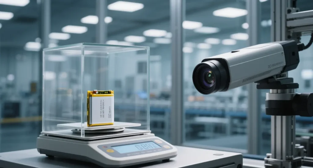
IV.Key Parameter Acquisition and Verification: A Practical Guide for Engineers
1. Accurate determination of coating porosity (ε_coat)
- Mercury-in-Pressure (MIP): most accurate, can measure pore size distribution, but equipment is expensive, may damage the sample
- Pipetting method:
- Steps: weigh dry wafer (m_dry) → immersed in electrolyte → removed and wiped dry and weighed (m_wet)
- Calculation: ε_coat = (m_wet – m_dry) / (ρ_electrolyte × V_coat)
- Rapid Production Evaluation: Combination of online thickness meter + surface density meter data real-time extrapolation Thickness meter + Surface Density Meter data back extrapolation in real time.
2. Reliability of diaphragm parameters
- Strictly based on supplier COA, focusing on:
- Thickness (δ_sep) tolerance: ±1μm level
- Porosity (ε_sep) range: 40±3%
- Third-party re-testing: Gurley value, SEM sampling on key batches
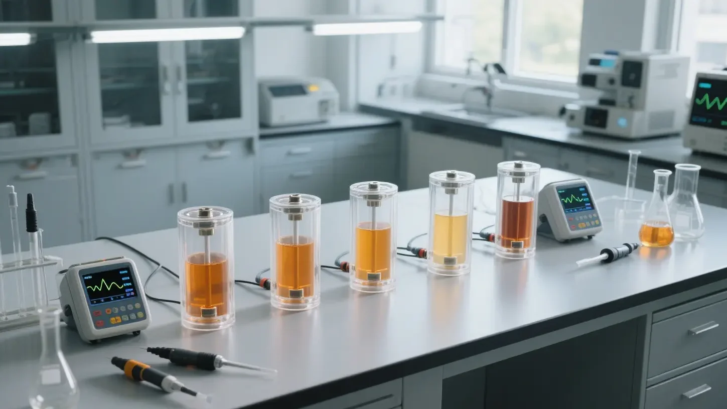
3. Experimental calibration of loss factor (α)
- Method: Make a battery with theoretical liquid filling volume → Cycle for 50-100 weeks → Disassemble and weigh the residual electrolyte
- Calculation: α = (m_initial – m_final) / (ρ_electrolyte × V_theoretical)
V. Frontier optimization: precise infiltration control beyond volume calculation
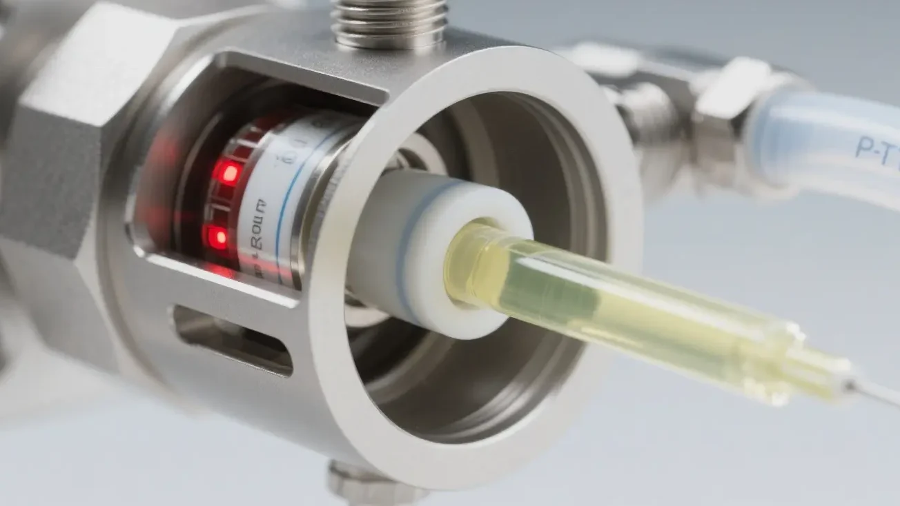
1. Pre-wetting process (Vacuum Filling):
Negative vacuum pressure ≤ -90 kPa → pore filling rate > 99% (reduce V_trap)
2. Electrolyte formulation optimization:
Reduce viscosity (e.g. add low-viscosity solvent FEC) → improve penetration speed, reduce liquid injection redundancy
3. Diaphragm/electrode surface modification:
hydrophilic coating (PVDF, Al₂O₃) → contact angle <10° → improve wetting efficiency, reduce V_margin
Engineer’s Insight: In the future, liquid injection accuracy will be upgraded from “volume control” to “real-time monitoring of interface wetting status” – via ultrasound imaging or Impedance Spectrum Analysis (ISA) to determine wetting uniformity online and realize dynamic closed loop liquid injection.